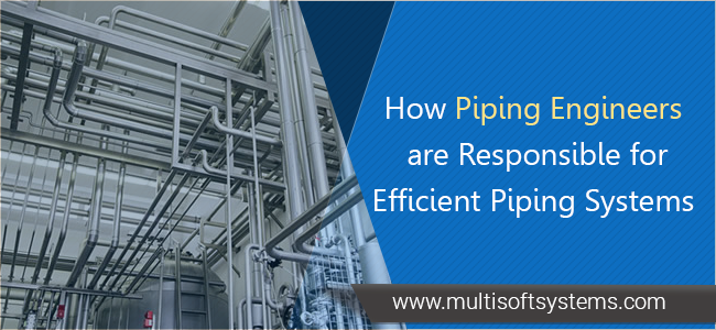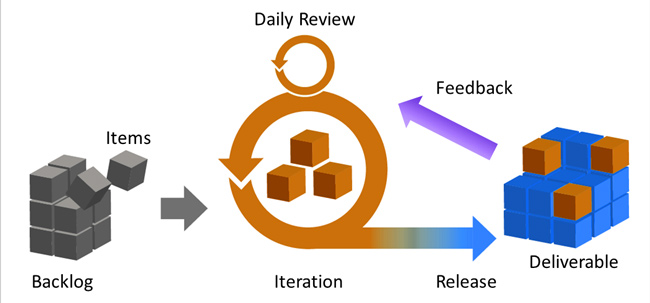


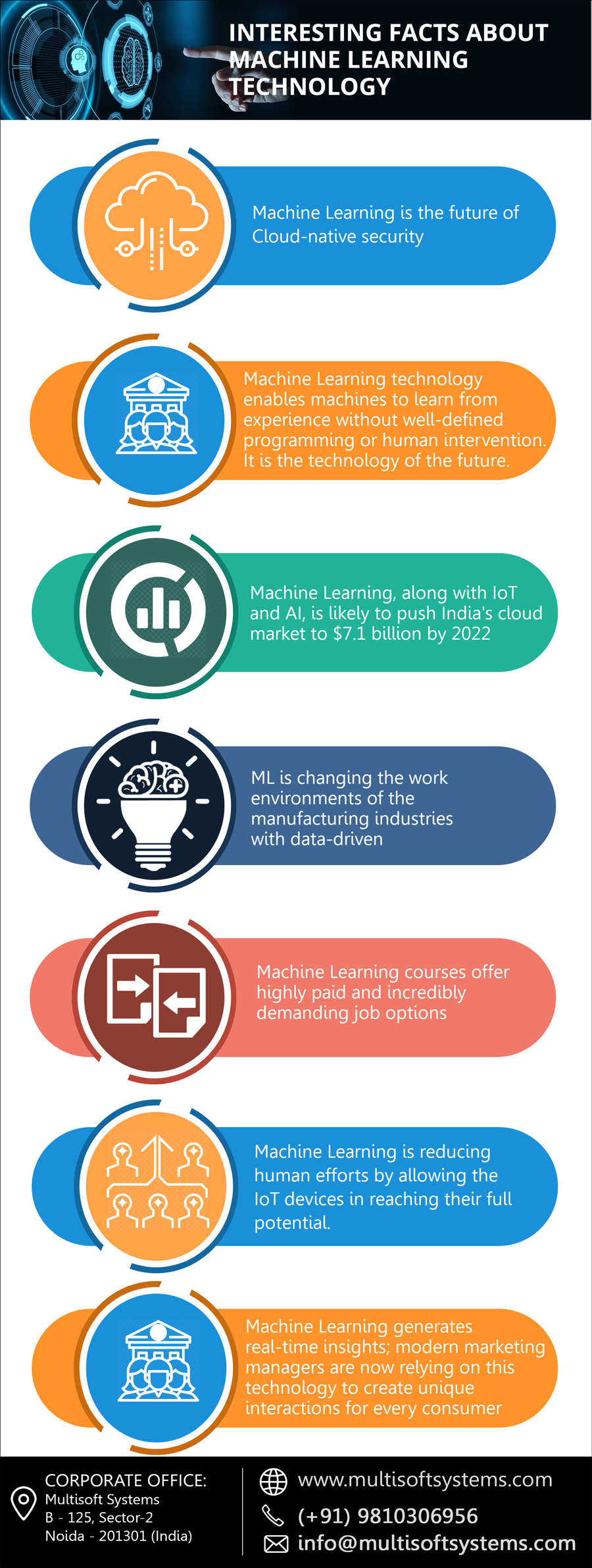
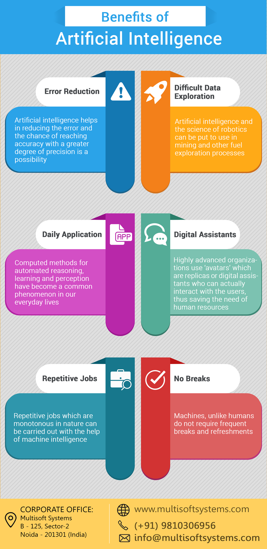
.png)


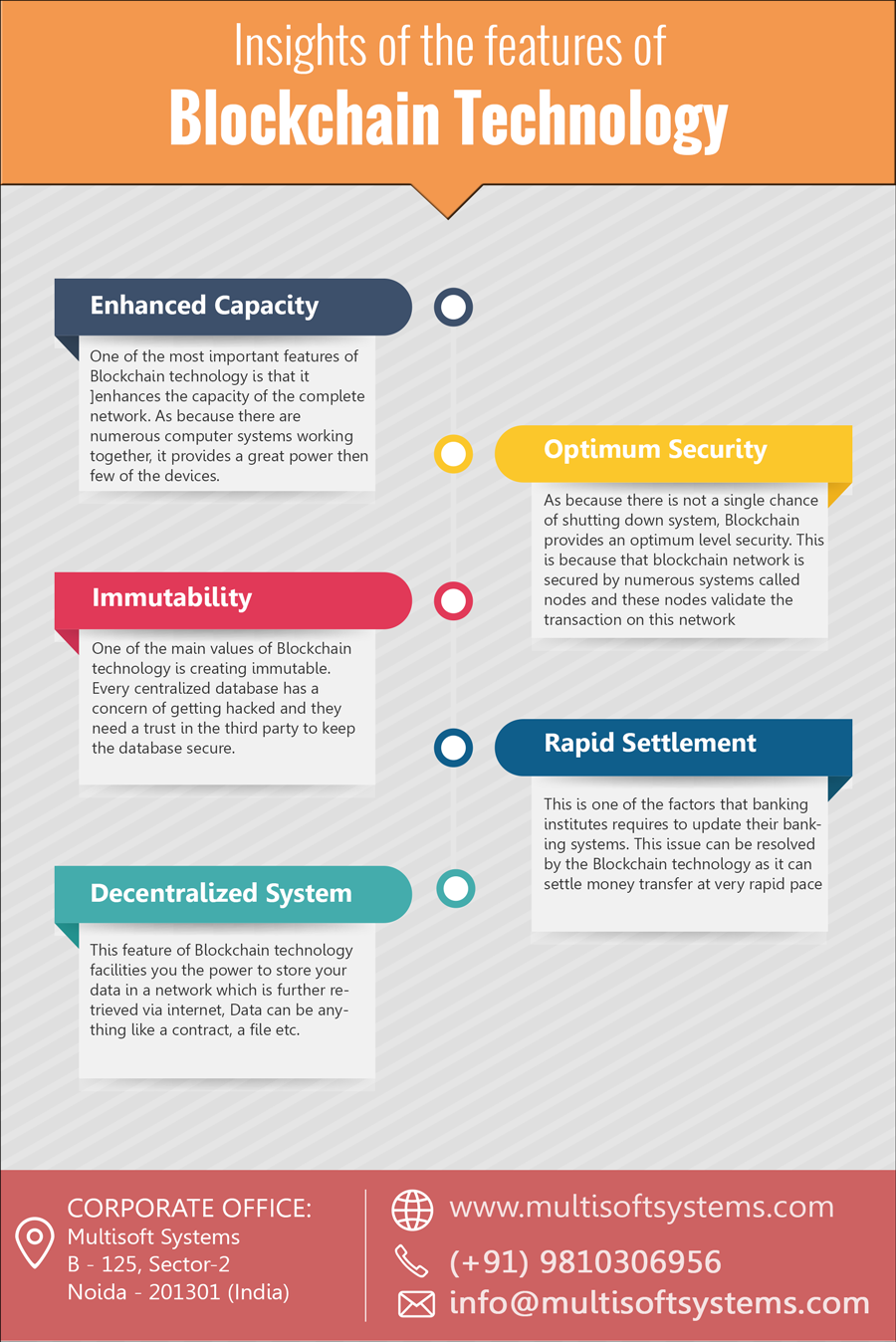
.png)


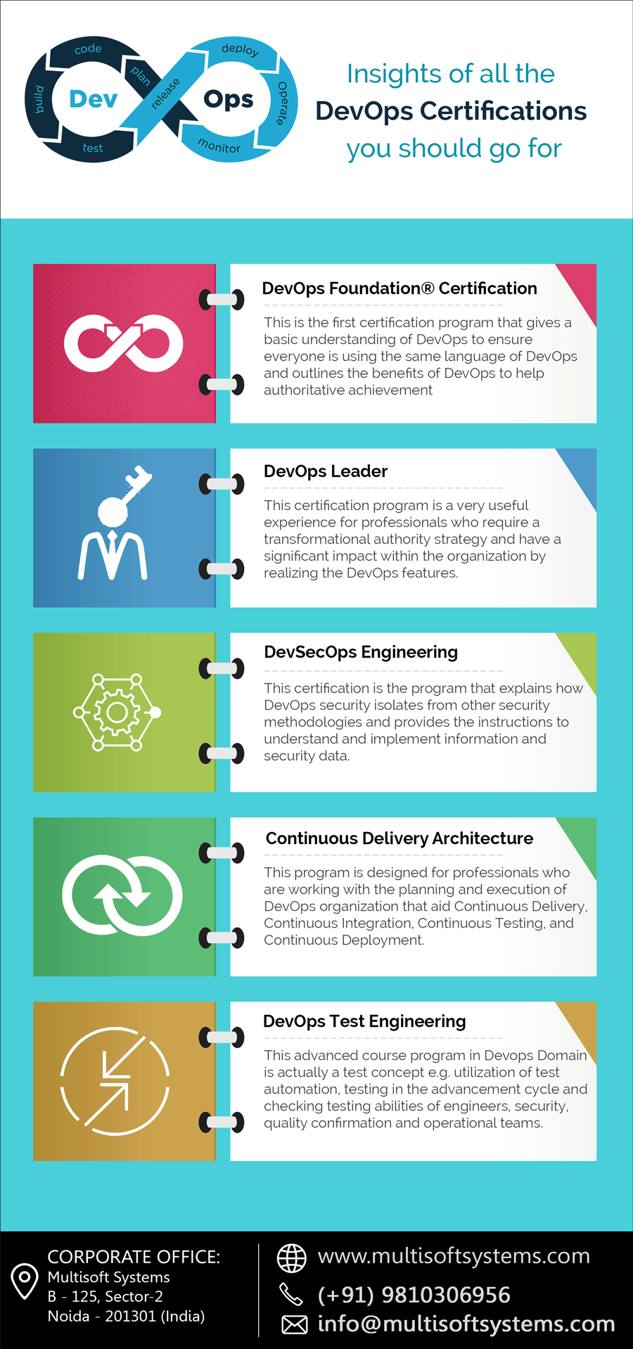
.png)


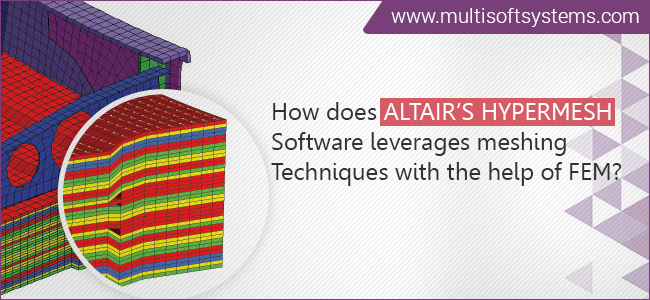
CAESAR II Training for Engineers: Learn Pipe Stress Analysis Like a Pro
September 29, 2025 Read More


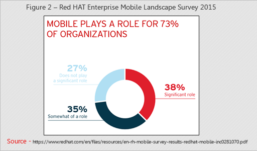
.jpg)


 Training.png)


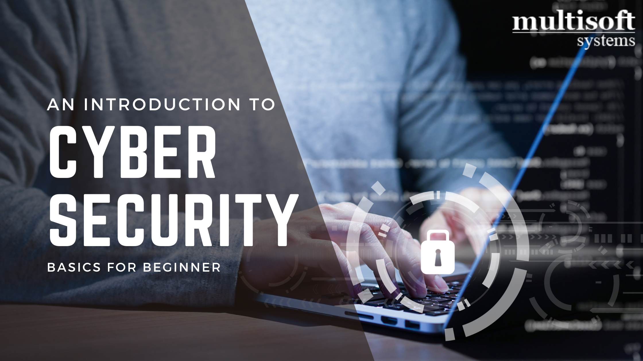


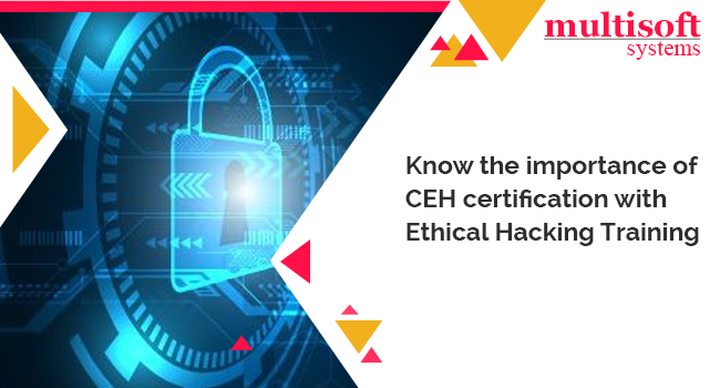


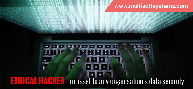
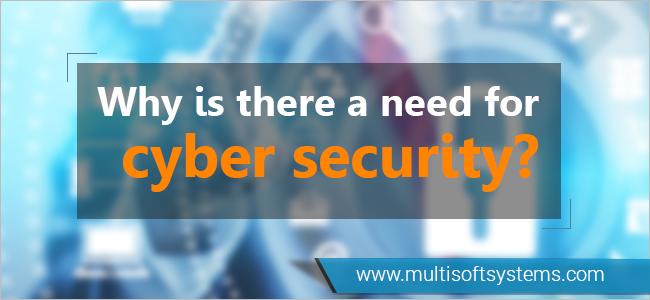
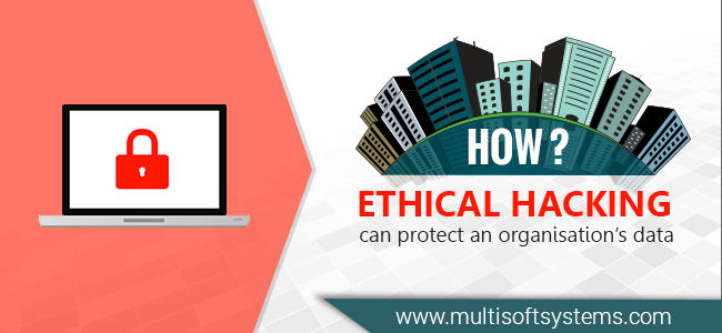
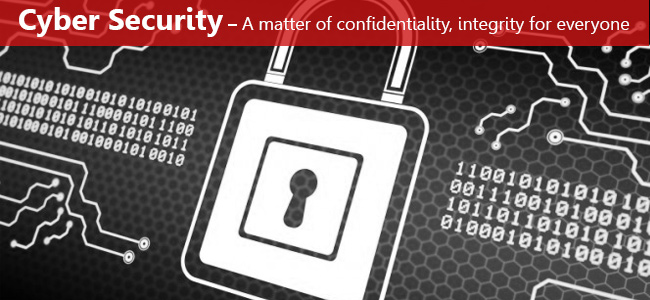
Become a proficient ethical hacker with Cyber security training program
September 10, 2018 Read More